Your Esp8266 circuit diagram images are ready. Esp8266 circuit diagram are a topic that is being searched for and liked by netizens today. You can Get the Esp8266 circuit diagram files here. Download all royalty-free images.
If you’re searching for esp8266 circuit diagram images information related to the esp8266 circuit diagram topic, you have pay a visit to the ideal site. Our website always provides you with suggestions for refferencing the highest quality video and image content, please kindly hunt and find more enlightening video articles and images that match your interests.
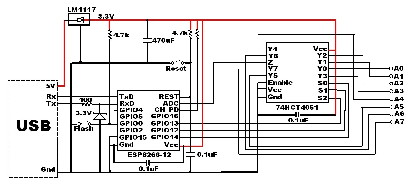
Esp8266 Circuit Diagram. The microcontroller turns itself down after executing a task. Once the code is released the switch can be released. Circuit Design for Programming ESP8266 using Arduino. As you can see the RF Transmitter Circuit consists of the Encoder IC and RF Receiver circuit consists of the Decoder ICSince the transmitter does not need a regulated 5V we have directly powered it with a 9V battery.
 Iot Based Patient Health Monitoring System Using Esp8266 And Arduino Iot Iot Projects Arduino From pinterest.com
The circuit charges the capacitor to a certain level. This way we can enter into the programming mode and upload the code. In the Getting Started with NodeMCU tutorial I talked about how to setup Arduino IDE for programming. Photodiode looks like a LED with a Black colour coating on its outer side. An integrator is connected in it and the capacitor discharges into this integrator or a low pass circuit. Circuit diagram of NodeMCU makes more clear about connections of NodeMCU with ESP8266 GPIO.
Arduino code for ESP8266 module.
Circuit diagram of NodeMCU makes more clear about connections of NodeMCU with ESP8266 GPIO. It is used in reversed biased as showed in circuit diagram below. The microcontroller turns itself down after executing a task. If youre not familiar with the Arduino it is an open-source electronics prototyping platform based on flexible easy-to-use hardware and softwareIt has a small microcontroller a USB port to connect to your computer for programming a power socket for providing power when the USB cable isnt connected and various. The circuit charges the capacitor to a certain level. Its the best choice for smart cities smart farms smart homes and IoT makers.
 Source: pinterest.com
If youre not familiar with the Arduino it is an open-source electronics prototyping platform based on flexible easy-to-use hardware and softwareIt has a small microcontroller a USB port to connect to your computer for programming a power socket for providing power when the USB cable isnt connected and various. Its the best choice for smart cities smart farms smart homes and IoT makers. An integrator is connected in it and the capacitor discharges into this integrator or a low pass circuit. The above block diagram shows a frequency to voltage converter. The LED is connected to pin GPIO2 of the ESP-01 module through a 330 ohm resistor.
 Source: gr.pinterest.com
The switch SW2 Programming Switch should be held pressed to hold the GPIO-0 pin to ground. Circuit Diagram Interfacing ESP8266-Nodemcu with IR sensor and LCD display. This way we can enter into the programming mode and upload the code. The above block diagram shows a frequency to voltage converter. LM358 is an operational amplifier Op-Amp and in this circuit we are using it as a voltage comparator.
 Source: pinterest.com
This device also gives stable results. The switch SW2 Programming Switch should be held pressed to hold the GPIO-0 pin to ground. Circuit diagram of NodeMCU makes more clear about connections of NodeMCU with ESP8266 GPIO. LM358 is an operational amplifier Op-Amp and in this circuit we are using it as a voltage comparator. ESP8266 WiFi Module.
 Source: pinterest.com
The above block diagram shows a frequency to voltage converter. WiFi Kit 8 is a classic IoT dev-board designed produced by Heltec AutomationTM its a highly integrated product based on ESP8266 Wi-Fi Li-Po battery management system 091 OLED is also included. This way we can enter into the programming mode and upload the code. The ESP-01 module needs a 33V supply. Follow the next tutorial to Install ESP8266 in Arduino IDE.
 Source: pinterest.com
ESP8266 NodeMCU PWM Pulse-Width Modulation The ESP8266 GPIOs can be set either to output 0V or 33V but they cant output any voltages in between. Circuit Diagram Interfacing ESP8266-Nodemcu with IR sensor and LCD display. WiFi Kit 8 is a classic IoT dev-board designed produced by Heltec AutomationTM its a highly integrated product based on ESP8266 Wi-Fi Li-Po battery management system 091 OLED is also included. Explore simple IoT Projects on Home Automation Internet of Things using Arduino ESP8266 ESP32 ESP32 CAM LoRa for engineering students. We can get the 33V for example from Arduino UNO board or using AMS1117 3V3 voltage regulator which steps down 5V into 33V or directly from 33V source.
 Source: pinterest.com
The ILI9341 TFT display board which is shown in project circuit diagram has 14 pins the first 9 pins are for the display and the other 5 pins are for the touch module. Circuit diagram is shown below. A simplified circuit diagram for using the ESP8266-01 module is given below. Circuit Diagram Interfacing ESP8266-Nodemcu with IR sensor and LCD display. Datacommand MOSI or SDI SCK clock BL back light LED and MISO or SDO.
 Source: pinterest.com
The microcontroller turns itself down after executing a task. ESP8266 WiFi Module. We can get the 33V for example from Arduino UNO board or using AMS1117 3V3 voltage regulator which steps down 5V into 33V or directly from 33V source. The Latching Power Switch Circuit also know as an Auto Power Off Circuit allows you to turn off your microcontroller via software whether youre using an ESP32 ESP8266 Arduino or any other board. The LED is connected to pin GPIO2 of the ESP-01 module through a 330 ohm resistor.
 Source: pinterest.com
Whereas in the receiver side we have used a 7805 5V voltage regulator to regulate 5V from the 9V battery. Circuit Diagram Interfacing ESP8266-Nodemcu with IR sensor and LCD display. Follow the next tutorial to Install ESP8266 in Arduino IDE. Block Diagram of F-V converter. It is used in reversed biased as showed in circuit diagram below.
 Source: in.pinterest.com
ESP8266 WiFi Module. Circuit diagram of NodeMCU makes more clear about connections of NodeMCU with ESP8266 GPIO. Arduino code for ESP8266 module. This way we can enter into the programming mode and upload the code. This circuit is specially useful to save power.
 Source: pinterest.com
This circuit is specially useful to save power. ESP8266 WiFi Module. Block Diagram of F-V converter. Now let us try to understand the design of the circuit. Whereas in the receiver side we have used a 7805 5V voltage regulator to regulate 5V from the 9V battery.
 Source: pinterest.com
The above block diagram shows a frequency to voltage converter. In the Getting Started with NodeMCU tutorial I talked about how to setup Arduino IDE for programming. LM358 is an operational amplifier Op-Amp and in this circuit we are using it as a voltage comparator. This way we can enter into the programming mode and upload the code. The switch SW2 Programming Switch should be held pressed to hold the GPIO-0 pin to ground.
 Source: pinterest.com
Before proceeding with this tutorial I strongly recommend you to go through the Getting Started with NodeMCU and also the NodeMCU Pinout tutorials as I discussed some of the basic yet very important topics related to ESP8266 NodeMCU Board. We can get the 33V for example from Arduino UNO board or using AMS1117 3V3 voltage regulator which steps down 5V into 33V or directly from 33V source. Its the best choice for smart cities smart farms smart homes and IoT makers. First and foremost the ESP8266 Module works on 33V Power Supply and anything greater than that like 5V for example will kill the SoC. Before proceeding with this tutorial I strongly recommend you to go through the Getting Started with NodeMCU and also the NodeMCU Pinout tutorials as I discussed some of the basic yet very important topics related to ESP8266 NodeMCU Board.
 Source: pinterest.com
The switch SW2 Programming Switch should be held pressed to hold the GPIO-0 pin to ground. The ESP-01 module needs a 33V supply. Circuit diagram is shown below. This happens for all the cycles of the input waveform. The switch SW2 Programming Switch should be held pressed to hold the GPIO-0 pin to ground.
 Source: cz.pinterest.com
Follow the next tutorial to Install ESP8266 in Arduino IDE. Circuit Diagram Interfacing ESP8266-Nodemcu with IR sensor and LCD display. A simplified circuit diagram for using the ESP8266-01 module is given below. Before proceeding with this tutorial you should have the ESP8266 add-on installed in your Arduino IDE. The ILI9341 TFT display board which is shown in project circuit diagram has 14 pins the first 9 pins are for the display and the other 5 pins are for the touch module.
 Source: pinterest.com
The circuit charges the capacitor to a certain level. The Latching Power Switch Circuit also know as an Auto Power Off Circuit allows you to turn off your microcontroller via software whether youre using an ESP32 ESP8266 Arduino or any other board. Before proceeding with this tutorial you should have the ESP8266 add-on installed in your Arduino IDE. The ILI9341 TFT display board which is shown in project circuit diagram has 14 pins the first 9 pins are for the display and the other 5 pins are for the touch module. Explore simple IoT Projects on Home Automation Internet of Things using Arduino ESP8266 ESP32 ESP32 CAM LoRa for engineering students.
 Source: pinterest.com
This happens for all the cycles of the input waveform. The switch SW2 Programming Switch should be held pressed to hold the GPIO-0 pin to ground. Before proceeding with this tutorial you should have the ESP8266 add-on installed in your Arduino IDE. Now let us try to understand the design of the circuit. We can get the 33V for example from Arduino UNO board or using AMS1117 3V3 voltage regulator which steps down 5V into 33V or directly from 33V source.
 Source: pinterest.com
This device also gives stable results. Photodiode looks like a LED with a Black colour coating on its outer side. A simplified circuit diagram for using the ESP8266-01 module is given below. The LM358 has two independent voltage comparators inside it which can be powered by single. Before proceeding with this tutorial I strongly recommend you to go through the Getting Started with NodeMCU and also the NodeMCU Pinout tutorials as I discussed some of the basic yet very important topics related to ESP8266 NodeMCU Board.

Follow the next tutorial to Install ESP8266 in Arduino IDE. You have already seen the required components and the circuit diagram of the project. A simplified circuit diagram for using the ESP8266-01 module is given below. VCC 5V GND ground CS chip select RST reset DC or DC. Datacommand MOSI or SDI SCK clock BL back light LED and MISO or SDO.
This site is an open community for users to share their favorite wallpapers on the internet, all images or pictures in this website are for personal wallpaper use only, it is stricly prohibited to use this wallpaper for commercial purposes, if you are the author and find this image is shared without your permission, please kindly raise a DMCA report to Us.
If you find this site beneficial, please support us by sharing this posts to your favorite social media accounts like Facebook, Instagram and so on or you can also save this blog page with the title esp8266 circuit diagram by using Ctrl + D for devices a laptop with a Windows operating system or Command + D for laptops with an Apple operating system. If you use a smartphone, you can also use the drawer menu of the browser you are using. Whether it’s a Windows, Mac, iOS or Android operating system, you will still be able to bookmark this website.


