Your Layout diagram of cmos inverter images are available. Layout diagram of cmos inverter are a topic that is being searched for and liked by netizens now. You can Find and Download the Layout diagram of cmos inverter files here. Get all free images.
If you’re searching for layout diagram of cmos inverter images information connected with to the layout diagram of cmos inverter keyword, you have visit the ideal blog. Our site always gives you suggestions for downloading the highest quality video and picture content, please kindly search and locate more informative video articles and images that fit your interests.
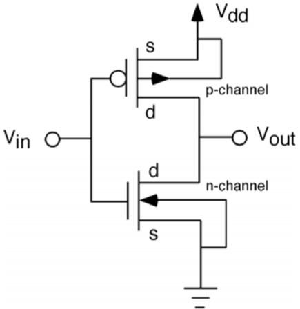
Layout Diagram Of Cmos Inverter. You just have to program the arduino board with the SPWM code as explained in the. The operation of CMOS inverter can be studied by using simple switch model of MOS transistor. Sticks Diagram 1 3 In Out V DD GND Stick diagram of inverter Dimensionless layout entities Only topology is important Final layout generated by compaction program. The 555 timer IC is an integrated circuit chip used in a variety of timer delay pulse generation and oscillator applications.
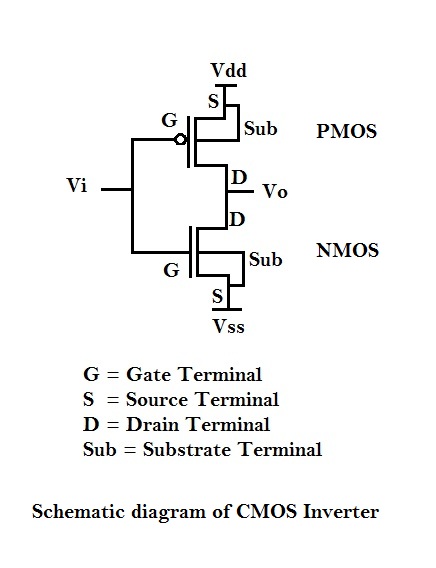 Switching Activity Of Cmos Vlsi System Design From vlsisystemdesign.com
The number of inverter stages in this oscillator mainly depends on the frequency which we want to generate from this oscillator. A bad layout can easily lead to unstable operation. VLSI - Switch Logic. Device Information1 PART NUMBER PACKAGE PINS BODY. In Boolean logic an inverter an AND gate. Layout of Logic gates.
Three Input NAND Gate.
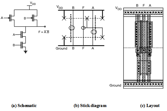
In this diagram virtually all of the elements shown are fundamentally necessary the exceptions being the shutdown control and saturation sensor functions shown dotted. Figure below shows the schematic stick diagram and layout of two input NAND gate implemented using complementary CMOS logic. VLSI - Switch Logic. Schematically a CMOS gate is depicted below. In CMOS inverter increasing the fan-out also increases the propagation delay. The designing of the ring oscillator can be done using three inverters.
 Source: researchgate.net
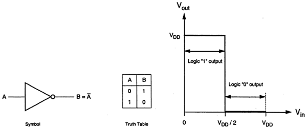
Table below shows the inverter truth table which shows that when there is 1 on the input then at the output there is 0 and vice-versa. 37 Full PDFs related to this paper. In CMOS inverter increasing the fan-out also increases the propagation delay. A short summary of this paper. You just have to program the arduino board with the SPWM code as explained in the.
 Source: khh.dnvrsmontani.pw
A more detailed look within a typical regulator block diagram reveals a variety of elements as is shown in Figure 92. Download Full PDF Package. While the symbol on a. Layout of Logic gates. 62 In CMOS inverter the propagation delay of a gate is thean _____ transition delay time for the signal during propagation from input to output especially when the signal changes its value.
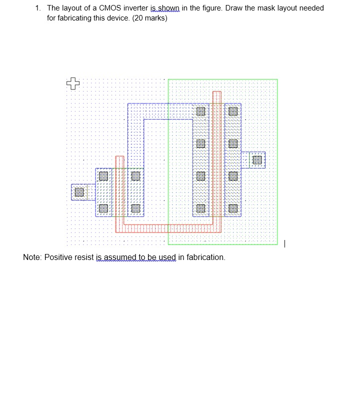 Source: chegg.com
A bad layout can easily lead to unstable operation. Figure below shows the schematic stick diagram and layout of three input NAND gate. Two Input NOR Gate. Figure below shows the schematic stick diagram and layout of two input NAND gate implemented using complementary CMOS logic. Layout of Logic gates.
 Source: book.huihoo.com
Layout of Logic gates. A regulated cascode circuit with low input impedance is used as the input stage of the TIA. Layout of Logic gates. In this case the separation between the polysilicon columns must allow diffusion-todiffusion separation in between. VLSI - Switch Logic.
 Source: tutorialspoint.com
Click here for a more detailed Diagram of the modular trunk cable components and a self-terminating layout. VLSI - Switch Logic. Ad Every Month We Help Millions Find the Best Power Inverter More. In Boolean logic an inverter an AND gate. Derivatives provide two or four timing circuits in one packageIt was commercialized in 1972 by Signetics.

Physical structure of CMOS devices and circuits pMOS and nMOS devices in a CMOS process n-well CMOS process device isolation Fabrication processes Physical design layout layout of basic digital gates masking layers design rules ssLecOOCoS pr planning complex layouts Euler Graph and Stick Diagram Part I. A NMH 1V and NML 1V b NMH 37V and NML 02V. A CMOS gate is a system consisting of a pMOS pull-up network connected to the output 1 or V DD and nMOS pull-down network connected to the output 0 or GND. The designing of the ring oscillator can be done using three inverters. Device Information1 PART NUMBER PACKAGE PINS BODY.
 Source: tutorialspoint.com
This inverter unambiguously demonstrates the most important trait of CMOS circuits that is low static-state power dissipation and thereby outperforms other logic circuit schemes such as. The NMOS device here is the minimum size device in this process and the inverter is therefore the smallest matched inverter possible. In the last article we learned how to generate sine wave pulse width modulation or SPWM though Arduino we are going to use the same Arduino board to make the proposed simple pure sine wave inverter circuitThe design is actually extremely straightforward as shown in the following figure. You just have to program the arduino board with the SPWM code as explained in the. The designing of the ring oscillator can be done using three inverters.
 Source: book.huihoo.com
Especially the layout hints. For any IC technology in the designing of digital circuits the basic element is the logic inverter. While the symbol on a. Stick Diagram VLSI - Design Rules Layout1 VLSI - Design Rules Layout2. Fan-out is a term that defines the maximum number of digital inputs that the output of a single logic gate can feed.
 Source: electronics-tutorial.net
A bad layout can easily lead to unstable operation. Download Full PDF Package. Note that wiring for CP-720 twin inverters has special considerations. While the symbol on a. A more detailed look within a typical regulator block diagram reveals a variety of elements as is shown in Figure 92.
 Source: youtube.com
Ad Every Month We Help Millions Find the Best Power Inverter More. A bad layout can easily lead to unstable operation. Numerous companies have made the original bipolar timers and similar low-power CMOS timers too. 62 In CMOS inverter the propagation delay of a gate is thean _____ transition delay time for the signal during propagation from input to output especially when the signal changes its value. The operation of CMOS inverter can be studied by using simple switch model of MOS transistor.
 Source: book.huihoo.com
Previously we discussed the simplest forms of. For any IC technology in the designing of digital circuits the basic element is the logic inverter. The CD4069UB device consist of six CMOS inverter circuits. If the inverter count is seven then it is seven stage ring oscillator. A regulated cascode circuit with low input impedance is used as the input stage of the TIA.
 Source: chegg.com
62 In CMOS inverter the propagation delay of a gate is thean _____ transition delay time for the signal during propagation from input to output especially when the signal changes its value. A short summary of this paper. Complementary metaloxidesemiconductor CMOS pronounced see-moss also known as complementary-symmetry metaloxidesemiconductor COS-MOS is a type of metaloxidesemiconductor field-effect transistor MOSFET fabrication process that uses complementary and symmetrical pairs of p-type and n-type MOSFETs for logic functions. Numerous companies have made the original bipolar timers and similar low-power CMOS timers too. Ad Every Month We Help Millions Find the Best Power Inverter More.
 Source: vlsisystemdesign.com
Physical structure of CMOS devices and circuits pMOS and nMOS devices in a CMOS process n-well CMOS process device isolation Fabrication processes Physical design layout layout of basic digital gates masking layers design rules ssLecOOCoS pr planning complex layouts Euler Graph and Stick Diagram Part I. Two Input NOR Gate. Layout of Logic gates. View the TI TIDA-01606 reference design block diagram schematic bill of materials BOM description features and design files and start designing. You just have to program the arduino board with the SPWM code as explained in the.
 Source: researchgate.net
A NMH 1V and NML 1V b NMH 37V and NML 02V. VLSI - Switch Logic VLSI - Gate Logic VLSI. Especially the layout hints. Download Full PDF Package. A CMOS gate is a system consisting of a pMOS pull-up network connected to the output 1 or V DD and nMOS pull-down network connected to the output 0 or GND.
 Source: studylib.net
Source: studylib.net
Derivatives provide two or four timing circuits in one packageIt was commercialized in 1972 by Signetics. VLSI - Switch Logic. Side-by-side cell placement forms a QCA array and is known as QCA wire as shown in Fig. CMOS DIGITAL INTEGRATED CIRCUITS BY SUNG MO KANG YUSUF LEBLEBICIprince367 Chaitanya Reddy. VLSI - Switch Logic VLSI - Gate Logic VLSI.
 Source: semanticscholar.org
You just have to program the arduino board with the SPWM code as explained in the. 37 Full PDFs related to this paper. For any IC technology in the designing of digital circuits the basic element is the logic inverter. CMOS DIGITAL INTEGRATED CIRCUITS BY SUNG MO KANG YUSUF LEBLEBICIprince367 Chaitanya Reddy. Complementary metaloxidesemiconductor CMOS pronounced see-moss also known as complementary-symmetry metaloxidesemiconductor COS-MOS is a type of metaloxidesemiconductor field-effect transistor MOSFET fabrication process that uses complementary and symmetrical pairs of p-type and n-type MOSFETs for logic functions.
 Source: ece-research.unm.edu
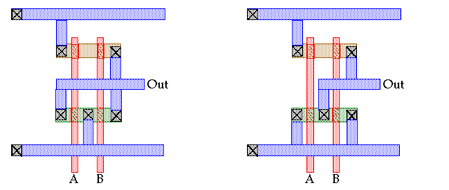
Numerous companies have made the original bipolar timers and similar low-power CMOS timers too. Layout Technique using Euler Graph Method. CMOS Inverter Layout A A. In 2017 it was said over a billion 555 timers are produced. Unlike conventional CMOS technology signal propagation is conducted based on cell-to-cell Coulomb interaction.
 Source: pdfslide.net
CMOS Inverter Layout A A. Figure below shows the schematic stick diagram and layout of three input NAND gate. Two Input NAND Gate. Fan-out is a term that defines the maximum number of digital inputs that the output of a single logic gate can feed. Schematically a CMOS gate is depicted below.
This site is an open community for users to do submittion their favorite wallpapers on the internet, all images or pictures in this website are for personal wallpaper use only, it is stricly prohibited to use this wallpaper for commercial purposes, if you are the author and find this image is shared without your permission, please kindly raise a DMCA report to Us.
If you find this site good, please support us by sharing this posts to your own social media accounts like Facebook, Instagram and so on or you can also bookmark this blog page with the title layout diagram of cmos inverter by using Ctrl + D for devices a laptop with a Windows operating system or Command + D for laptops with an Apple operating system. If you use a smartphone, you can also use the drawer menu of the browser you are using. Whether it’s a Windows, Mac, iOS or Android operating system, you will still be able to bookmark this website.


