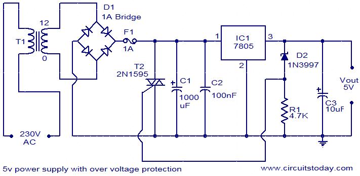
Your Power supply circuit diagram images are available. Power supply circuit diagram are a topic that is being searched for and liked by netizens today. You can Find and Download the Power supply circuit diagram files here. Get all royalty-free photos.
If you’re searching for power supply circuit diagram images information linked to the power supply circuit diagram keyword, you have visit the ideal blog. Our website always provides you with suggestions for viewing the highest quality video and picture content, please kindly hunt and locate more enlightening video content and graphics that fit your interests.
Power Supply Circuit Diagram. Huge heat sink is required in this circuit as 2N3055 transistors produce large. Regulated Power Supply. October 27 2020 February 24 2012 by Electrical4U. Class A power amplifier circuit.
 Unregulated Powersupply Circuit Diagram Electrical Electronics Circuit Diagram Block Diagram Diagram From in.pinterest.com
This diagram is a wiring diagram for 3 DVC drivers with dual 6 ohm coils. Class A power amplifier circuit. For USB powering the KL26 interface processor has an on-board regulator that brings the external USB voltage into the correct range for the microbit board. Find new and used cars for sale on MSN Autos Marketplace. Make sure that your amplifier can handle this load if. October 27 2020 February 24 2012 by Electrical4U.
0-28V 6-8A Power Supply Circuit Diagram using LM317 and 2N3055.
This PSU uses an LM723 as the regulator 4 parallel connected outboard pass transistors and has current limiting above 25 amps. This design can produce a current of 20 amps with little modification use proper rating transformer and a huge heat sink with fan. It will consist of electrical connections power sources switches wire joints etc. Find new and used cars for sale on MSN Autos Marketplace. The basic circuit includes a Reset Circuit the oscillator circuit and power supply. Regulated Power Supply.
 Source: pinterest.com
This change cuts-off the current supply from supply source 1 and switches to the supply source 2. The State of Texas Cooperative Purchasing Program available for local governments education and non-profit assistance organizations is now called the Texas SmartBuy Membership Program. Pins 40 and 20 VCC and GND of the 8051 Microcontroller are connected to 5V and GND respectively. Regulated Power Supply. The basic circuit includes a Reset Circuit the oscillator circuit and power supply.
 Source: pinterest.com
Make sure that your amplifier can handle this load if. A series RLC circuit is one the resistor inductor and capacitor are connected in series across a voltage supply. We would like to show you a description here but the site wont allow us. The centre tapped describes the voltage output of. Converting 220v AC into 12v AC using Step Down Transformer.
 Source: pinterest.com
This diagram is a wiring diagram for 3 DVC drivers with dual 6 ohm coils. Gain access to purchase from State of Texas contracts and procurement resources by becoming a purchasing memberPut the states multi-billion dollar purchasing power to work for you. Circuit diagrams illustrate how electrical circuits are composed. We would like to show you a description here but the site wont allow us. Power to the microbit can be provided by 3 sources.
 Source: pinterest.com
This design can produce a current of 20 amps with little modification use proper rating transformer and a huge heat sink with fan. A wiring diagram is simply a pictorial representation of all the electrical connections in a specific circuit. Andy Collinson Email. Description A 12 Volt high current 20 Amp power supply. Converting 220v AC into 12v AC using Step Down Transformer.
 Source: pinterest.com
But what if need to vary the power supply voltage so here we have Variable Voltage Regulator IC LM317. Huge heat sink is required in this circuit as 2N3055 transistors produce large. For USB powering the KL26 interface processor has an on-board regulator that brings the external USB voltage into the correct range for the microbit board. A series RLC circuit is one the resistor inductor and capacitor are connected in series across a voltage supply. Circuit Diagram Types.
 Source: pinterest.com
Converting 220v AC into 12v AC using Step Down Transformer. Next is the Reset Circuit. For USB powering the KL26 interface processor has an on-board regulator that brings the external USB voltage into the correct range for the microbit board. This change cuts-off the current supply from supply source 1 and switches to the supply source 2. They provide a fixed regulated power supply.

These diagrams are an effective way of showing how wires are interconnected with different components in a system. Circuit diagrams are used by professionals to design construct and maintain circuits in rooms or structures. Pins 40 and 20 VCC and GND of the 8051 Microcontroller are connected to 5V and GND respectively. The State of Texas Cooperative Purchasing Program available for local governments education and non-profit assistance organizations is now called the Texas SmartBuy Membership Program. The output voltage is variable from 122 Volt to 144V so can be set for any device requiring voltage and current in that range.
 Source: pinterest.com
Make sure that your amplifier can handle this load if. A wiring diagram is simply a pictorial representation of all the electrical connections in a specific circuit. The circuit diagram of a. Andy Collinson Email. We would like to show you a description here but the site wont allow us.
 Source: pinterest.com
This design can produce a current of 20 amps with little modification use proper rating transformer and a huge heat sink with fan. A regulated power supply converts unregulated AC Alternating Current to a constant DC Direct Current. Make sure that your amplifier can handle this load if. All of the voice coils are wired in parallel for a 1 ohm load. The circuit diagram of a.
 Source: pinterest.com
This PSU uses an LM723 as the regulator 4 parallel connected outboard pass transistors and has current limiting above 25 amps. The resulting circuit is called series RLC circuitA circuit and phasor diagram for a series RLS circuit has been shown below. Find new and used cars for sale on MSN Autos Marketplace. For USB powering the KL26 interface processor has an on-board regulator that brings the external USB voltage into the correct range for the microbit board. What is a Regulated Power Supply.
 Source: pinterest.com
October 27 2020 February 24 2012 by Electrical4U. The primary terminals of the centre tapped transformer is connected with household supply 220V ac 50Hz and output is taken from secondary terminals of the transformer. Class D and high current class AB amplifiers are probably the only amplifiers that can handle this load. This PSU uses an LM723 as the regulator 4 parallel connected outboard pass transistors and has current limiting above 25 amps. Students are also taught to use electrical diagrams to understand basic principles of power and electricity.
 Source: ro.pinterest.com
Let us discuss a little bit deeper about this basic circuit of 8051 Microcontroller. Circuit diagrams are used by professionals to design construct and maintain circuits in rooms or structures. The current supply source 2 supplies a reverse current to the integrator so that its output drops linearly with time. The State of Texas Cooperative Purchasing Program available for local governments education and non-profit assistance organizations is now called the Texas SmartBuy Membership Program. Power to the microbit can be provided by 3 sources.
 Source: pinterest.com
Circuit diagrams are used by professionals to design construct and maintain circuits in rooms or structures. These diagrams are an effective way of showing how wires are interconnected with different components in a system. First is the power supply. The resulting circuit is called series RLC circuitA circuit and phasor diagram for a series RLS circuit has been shown below. The wiring diagram shows different components in a circuit via different shapes and symbols.
 Source: pinterest.com
Converting 220v AC into 12v AC using Step Down Transformer. For USB powering the KL26 interface processor has an on-board regulator that brings the external USB voltage into the correct range for the microbit board. The centre tapped describes the voltage output of. Circuit Diagram Types. October 27 2020 February 24 2012 by Electrical4U.
 Source: pinterest.com
October 27 2020 February 24 2012 by Electrical4U. They provide a fixed regulated power supply. Regulated Power Supply. A series RLC circuit is one the resistor inductor and capacitor are connected in series across a voltage supply. The basic circuit includes a Reset Circuit the oscillator circuit and power supply.
 Source: pinterest.com
But what if need to vary the power supply voltage so here we have Variable Voltage Regulator IC LM317. These diagrams are an effective way of showing how wires are interconnected with different components in a system. We would like to show you a description here but the site wont allow us. Let us discuss a little bit deeper about this basic circuit of 8051 Microcontroller. The resulting circuit is called series RLC circuitA circuit and phasor diagram for a series RLS circuit has been shown below.
 Source: pinterest.com
A series RLC circuit is one the resistor inductor and capacitor are connected in series across a voltage supply. Get a great deal on a great car and all the information you need to make a smart purchase. The output voltage is variable from 122 Volt to 144V so can be set for any device requiring voltage and current in that range. Pins 40 and 20 VCC and GND of the 8051 Microcontroller are connected to 5V and GND respectively. What is a Regulated Power Supply.
 Source: in.pinterest.com
Regulated Power Supply. For USB powering the KL26 interface processor has an on-board regulator that brings the external USB voltage into the correct range for the microbit board. Class D and high current class AB amplifiers are probably the only amplifiers that can handle this load. A wiring diagram is simply a pictorial representation of all the electrical connections in a specific circuit. The current supply source 2 supplies a reverse current to the integrator so that its output drops linearly with time.
This site is an open community for users to do sharing their favorite wallpapers on the internet, all images or pictures in this website are for personal wallpaper use only, it is stricly prohibited to use this wallpaper for commercial purposes, if you are the author and find this image is shared without your permission, please kindly raise a DMCA report to Us.
If you find this site adventageous, please support us by sharing this posts to your favorite social media accounts like Facebook, Instagram and so on or you can also bookmark this blog page with the title power supply circuit diagram by using Ctrl + D for devices a laptop with a Windows operating system or Command + D for laptops with an Apple operating system. If you use a smartphone, you can also use the drawer menu of the browser you are using. Whether it’s a Windows, Mac, iOS or Android operating system, you will still be able to bookmark this website.


